What Is a Laser Cutting Machine and How Does It Work?
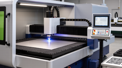
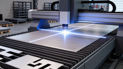
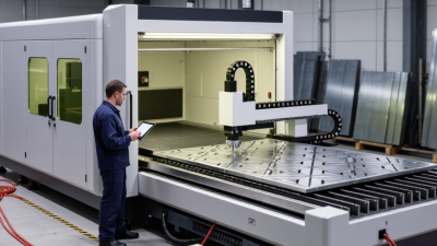
A laser cutting machine turns concentrated light into a precise manufacturing tool. It cuts, engraves, or marks materials by directing a focused laser beam across a programmed path. The beam can melt, burn, or vaporize a tiny area, while assist gas clears debris from the cut. The result is often a clean edge with limited physical contact.
Theodore H. Maiman, inventor of the first working laser, famously described it as “a solution looking for a problem.” That observation still feels relevant. A laser cutting machine is powerful, but it is not automatically the best choice for every material or production task. Thickness, reflectivity, heat sensitivity, tolerances, and operating costs all influence the outcome. A beautiful sample cut can hide poor settings.
Inside the system, a laser source generates the beam. Mirrors or fiber delivery guide it toward a cutting head. A focusing lens concentrates the energy onto the workpiece. CNC software then controls movement along the planned design. Even a small focus error can leave rough edges, excessive heat, or incomplete penetration.
This guide explains how each stage works, from beam generation to finished cut. It also examines common laser types, machine components, material behavior, and safety controls. The process may look almost effortless through a viewing window. It is not. Good results depend on calibrated optics, stable motion, suitable parameters, and experienced judgment. Mistakes remain useful teachers, but they should never replace documented procedures and responsible operation.
Laser Types and Wavelengths: CO₂ at 10.6 µm, Fiber at 1.06–1.08 µm
A laser cutting machine focuses a high-energy beam onto a programmed path. The beam melts, burns, or vaporizes material, while an assist gas removes debris. Motion-control software guides the cutting head with millimeter-level precision. Grand View Research’s 2024 market report estimated the global laser cutting machine market at approximately USD 7.3 billion in 2023, reflecting broad industrial adoption.
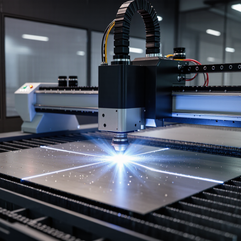
Wavelength decides how efficiently a material absorbs energy. CO₂ lasers operate near 10.6 µm, where wood, acrylic, paper, textiles, and many nonmetals absorb strongly. Their longer wavelength can produce clean edges on thick organic sheets, although heat-affected zones may widen. Fiber lasers usually emit between 1.06 and 1.08 µm. This shorter wavelength couples efficiently with steel, aluminum, brass, and copper. The 2024 Industrial Laser Solutions market review describes fiber technology as a major driver in metal-processing applications, especially for thin and medium-gauge sheets.
The wavelength is not the whole answer. Beam quality, spot size, power density, focal position, material coating, and assist-gas pressure also control the cut. NIST spectral data supports the basic absorption differences, but real workshops often show less predictable results. Reflective metals can redirect energy toward the optics. Dirty lenses can distort the beam. Operators should verify settings through test coupons, not rely on a chart alone. That practical step is easy to skip. It should not be.
Beam Generation and Power Control in Industrial 1–20 kW Laser Systems
What Is a Laser Cutting Machine and How Does It Work?
Beam Generation and Power Control in Industrial 1–20 kW Laser Systems
An industrial laser cutting machine converts electrical energy into a concentrated light beam. In many 1–20 kW systems, pump diodes energize a gain fiber. The fiber amplifies the light through stimulated emission. A resonator and optical isolators help maintain stable beam production. The resulting beam travels through a delivery fiber toward the cutting head.
Power control is more than turning the laser on or off. A controller adjusts diode current, pulse timing, and duty cycles within milliseconds. Sensors monitor output power, temperature, and reflected light. Feedback systems then correct small changes before they affect the cut. At higher power, beam quality and focus position become critical. A slight focal shift can widen the kerf or leave rough edges.
In practical production, material thickness, alloy, speed, and assist gas must be balanced carefully. More power does not always mean better cutting. It can increase heat-affected zones, dross, and operating costs. Clean optics matter. So does calibration. Even well-designed systems can behave imperfectly when lenses heat unevenly or sensors drift. Operators should verify power at the workpiece, not trust displayed values blindly. That habit is simple. It is often overlooked.
Industrial Laser Systems: Nominal Continuous-Wave Output Power
Industrial fiber laser systems are commonly specified by their continuous-wave optical output power.
Higher power can increase cutting capacity and productivity, but actual results also depend on material type, thickness, beam quality, focus diameter, assist gas, and cutting parameters.
Beam Delivery and Focusing for a Typical 0.1–0.5 mm Cutting Kerf
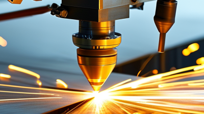
A laser cutting machine uses a concentrated light beam to melt, burn, or vaporize material along a programmed path. The beam travels from the laser source through a delivery system. Depending on the machine, this path may use sealed mirrors or an optical fiber. A collimator keeps the beam organized. The cutting head then directs it toward the workpiece.
The focusing lens creates a narrow waist near the material surface. This small spot controls the cut width, commonly producing a kerf between 0.1 and 0.5 mm. The nozzle surrounds the beam and sends assist gas through the cutting zone. Oxygen can support cutting in some steels, while nitrogen often reduces oxidation on stainless steel. Focus position matters greatly. A slight offset can leave a rough lower edge or incomplete separation.
Real production work is less perfect than diagrams suggest. Dust on the lens, thermal drift, and uneven sheet thickness can change the kerf during a shift. I have seen a clean test cut become rough after several hours of operation. Measuring the actual slot with a microscope or precision gauge is more reliable than trusting the display settings. Feed speed, power, gas pressure, and focus must be checked together. The smallest kerf is not always the best result. A narrow cut may still show excessive taper, dross, or heat damage. Careful operators record these details, then adjust one variable at a time.
Material Removal Through Melting, Burning, and Sublimation
A laser cutting machine uses a concentrated beam of light to remove material along a programmed path. Mirrors or fiber optics guide the beam toward a lens, which focuses it into a tiny, intense spot. At that point, the material absorbs energy and changes rapidly. The result is a narrow cut, called a kerf.
Melting is common with metals and many plastics. The beam raises the surface above its melting point, while assist gas pushes liquid material away. Burning involves a controlled chemical reaction, often oxidation, that adds heat and helps cut thicker steel. Sublimation works differently. The material changes directly from solid to vapor, leaving little liquid residue. Wood, some polymers, and delicate films can respond this way under suitable settings.
In practical work, speed, power, focus, and gas pressure must match the material. Too much energy can create wide kerfs, rough edges, or dark heat marks. Too little energy may leave an incomplete cut. I have found that a clean-looking edge can still hide internal stress, especially in thin sheets. That detail is easy to miss. Operators should inspect the underside, measure the kerf, and test a small sample before production. Moisture, coatings, and surface texture also affect absorption, so identical thicknesses may require different settings. The process feels precise, but it is not automatic.
CNC Motion, Assist Gases, and Positioning Accuracy Near ±0.05 mm
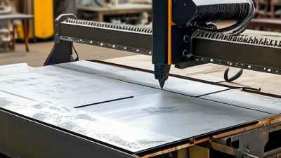
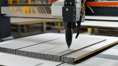
A laser cutting machine uses a focused beam to melt, burn, or vaporize material along a programmed path. Its CNC controller moves the cutting head across X, Y, and sometimes Z axes. Smooth acceleration helps maintain consistent kerf width around corners and small holes. Positioning accuracy near ±0.05 mm is possible on well-calibrated equipment under controlled conditions. It is not a promise for every job.
Assist gases shape the cutting process. Oxygen can support faster cutting in mild steel, while nitrogen helps protect stainless steel from heavy oxidation. Air may reduce operating cost, but it can leave a different edge finish. Gas pressure, nozzle height, lens condition, and sheet flatness all influence results. A clean nozzle matters.
In practical operation, I would check the focus position before judging CNC accuracy. A tiny height error can create a wide, rough edge, even when the programmed coordinates are correct. Thermal distortion can also move thin sheets during cutting. That matters. Operators often verify dimensions with calipers and test patterns before production. Machine accuracy and part accuracy are related, but they are not identical. I have seen excellent positioning figures produce disappointing parts after poor fixturing. This is where specifications need careful interpretation. Calibration records, repeatability tests, and measured samples provide stronger evidence than a single brochure number.